Services > Advanced Field Testing > Yield Loss Investigation & Root Cause Analysis
Yield Loss Investigation & Root Cause Analysis
Have a Question or Need Assistance?

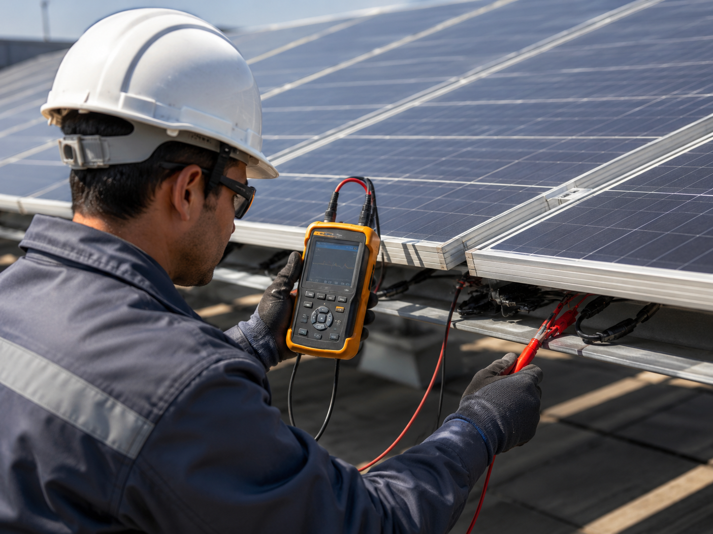
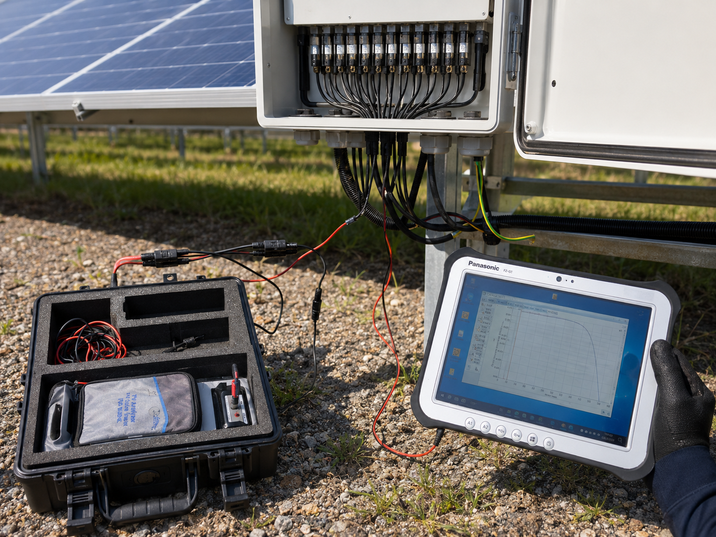

Find where performance losses are coming from
When a solar PV system produces less energy than expected, the cause is not always obvious. The issue may sit at module level, string level, inverter block level, or somewhere in the site design, installation, or operating conditions.
Some problems are visible. Others only appear through thermal patterns, EL images, IV curves, or targeted checks for hidden electrical defects. A yield loss investigation helps move the discussion from “the system is underperforming” to a clearer view of what is happening, where it is happening, and what should be checked next.
Intertek CEA combines field inspection methods to help owners, operators, investors, and EPCs understand performance losses and make better repair, warranty, or remediation decisions.
When this inspection helps
Use this page for situations like:
The solar PV system is producing less energy than expected.
Performance losses are visible in monitoring data, but the cause is unclear.
A drop in yield appeared after site work, maintenance, cleaning, storms, or other events.
Losses appear concentrated in certain strings, rows, inverter blocks, or areas of the site.
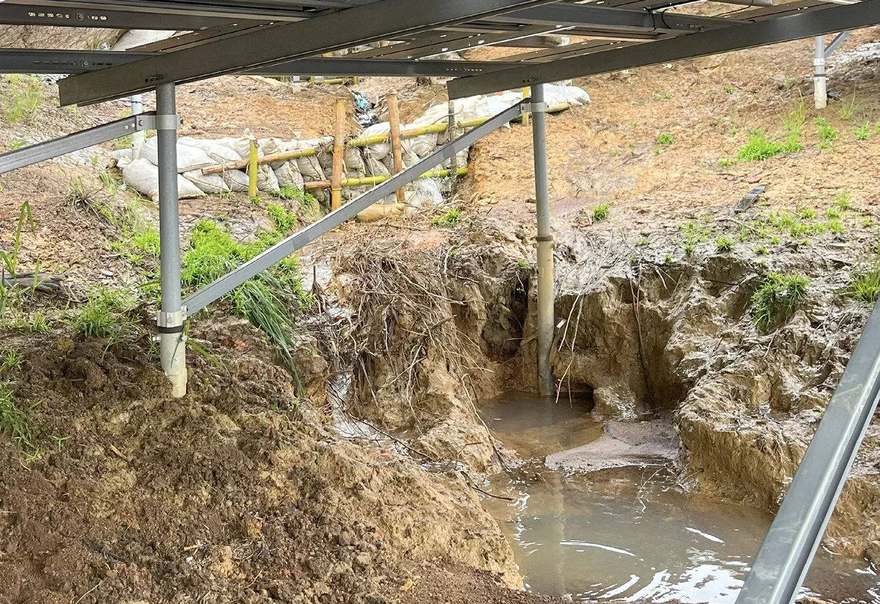
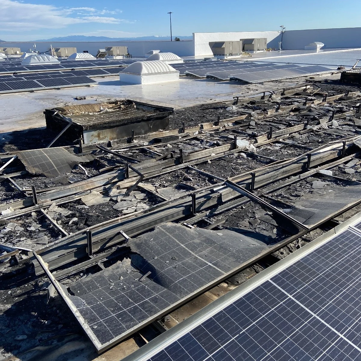
Modules show hotspots, visible changes, cracks, corrosion, or other signs of degradation.
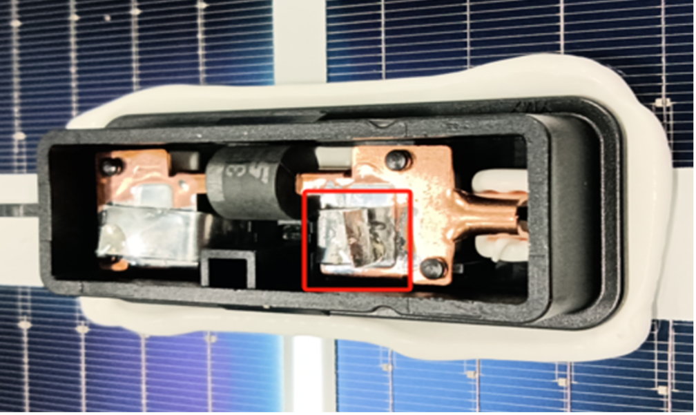
Lost bypass diodes or other hidden electrical defects are suspected.
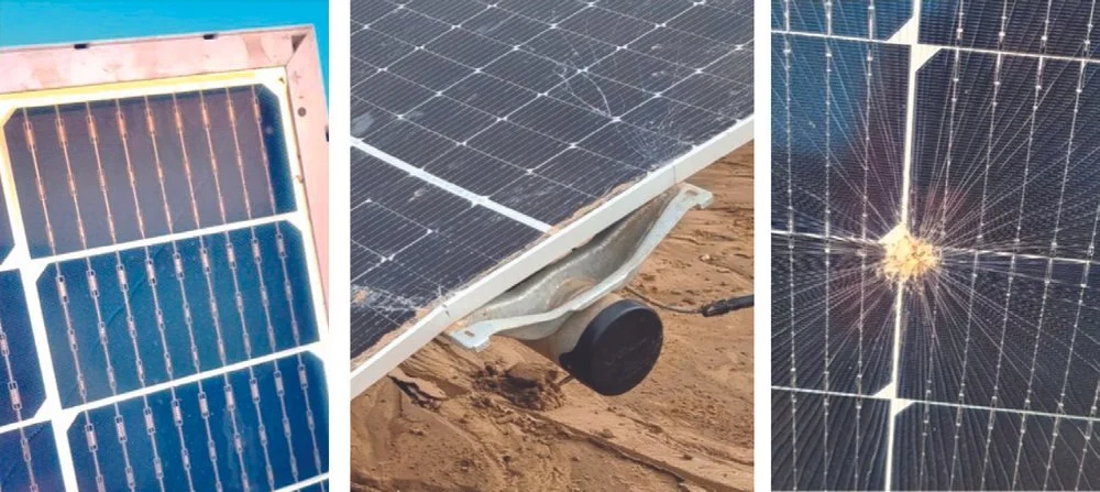
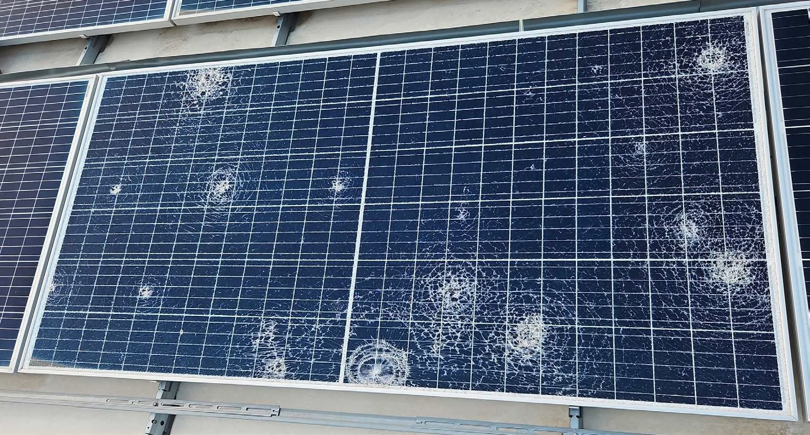
Glass breakage may be contributing to performance loss or safety risk.
You need evidence for warranty discussions, repair planning, or internal technical review.
How we decide the right scope
The final inspection plan depends on the loss pattern, the suspected cause, and what decision the results need to support.
1. What does the performance loss look like?
A sudden drop may point to a recent event, site work, equipment change, or electrical fault. A gradual decline may point to degradation, soiling, shading, recurring module issues, or aging effects. The inspection scope should start with the pattern of the loss.
2. Where is the loss concentrated?
If the loss appears across the full site, the investigation may need broad screening. If it is concentrated in specific strings, rows, tables, or inverter blocks, targeted testing may be more useful.
3. Are thermal patterns visible?
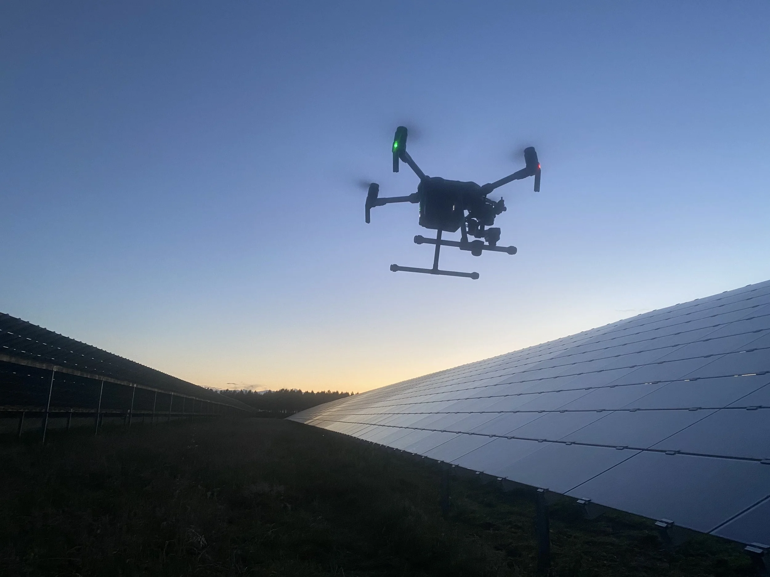
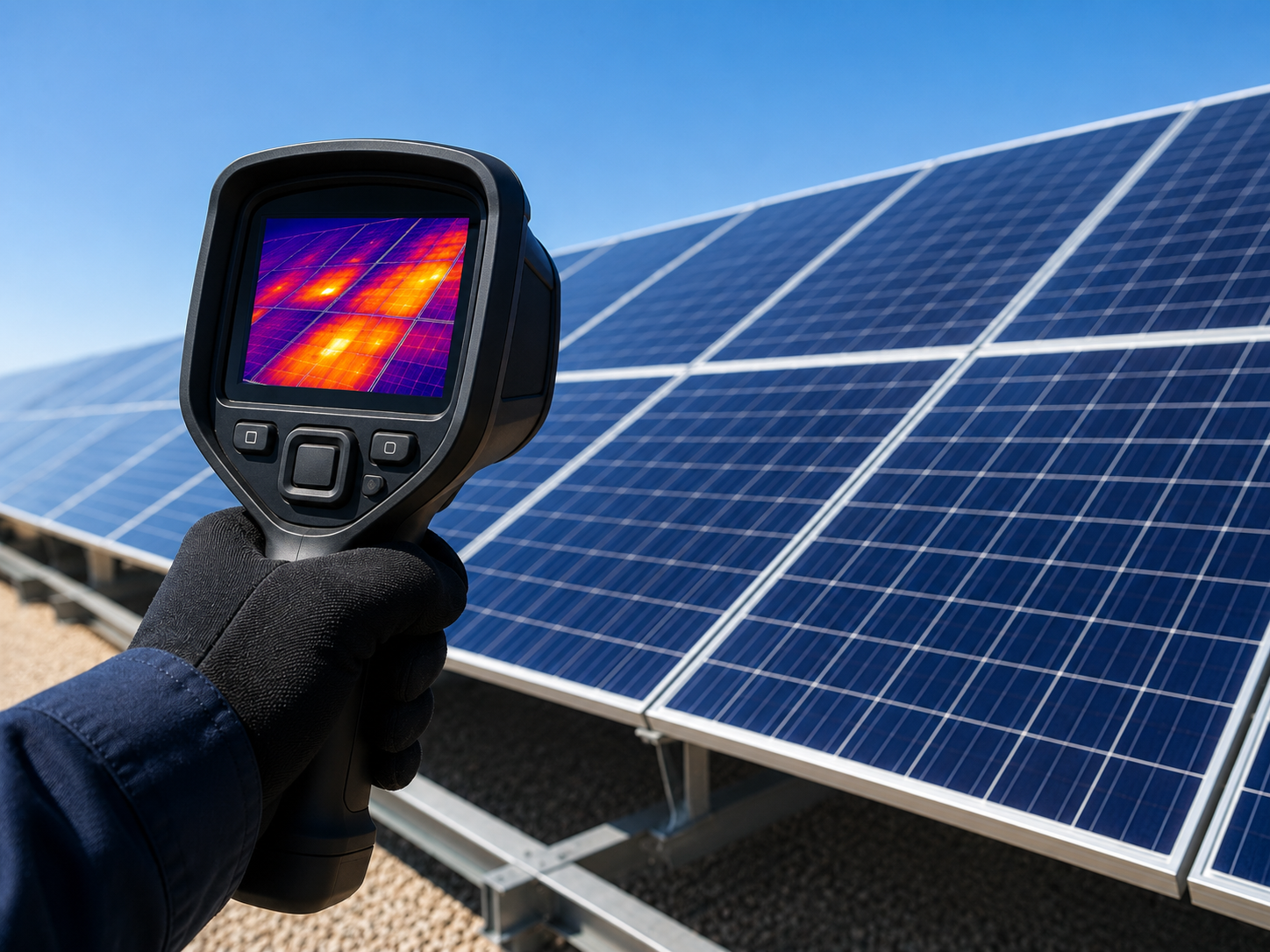
IR thermography can help identify hotspots, failed substrings, affected strings, or recurring thermal patterns that may explain part of the yield loss and guide follow-up testing.
4. Is hidden module damage suspected?
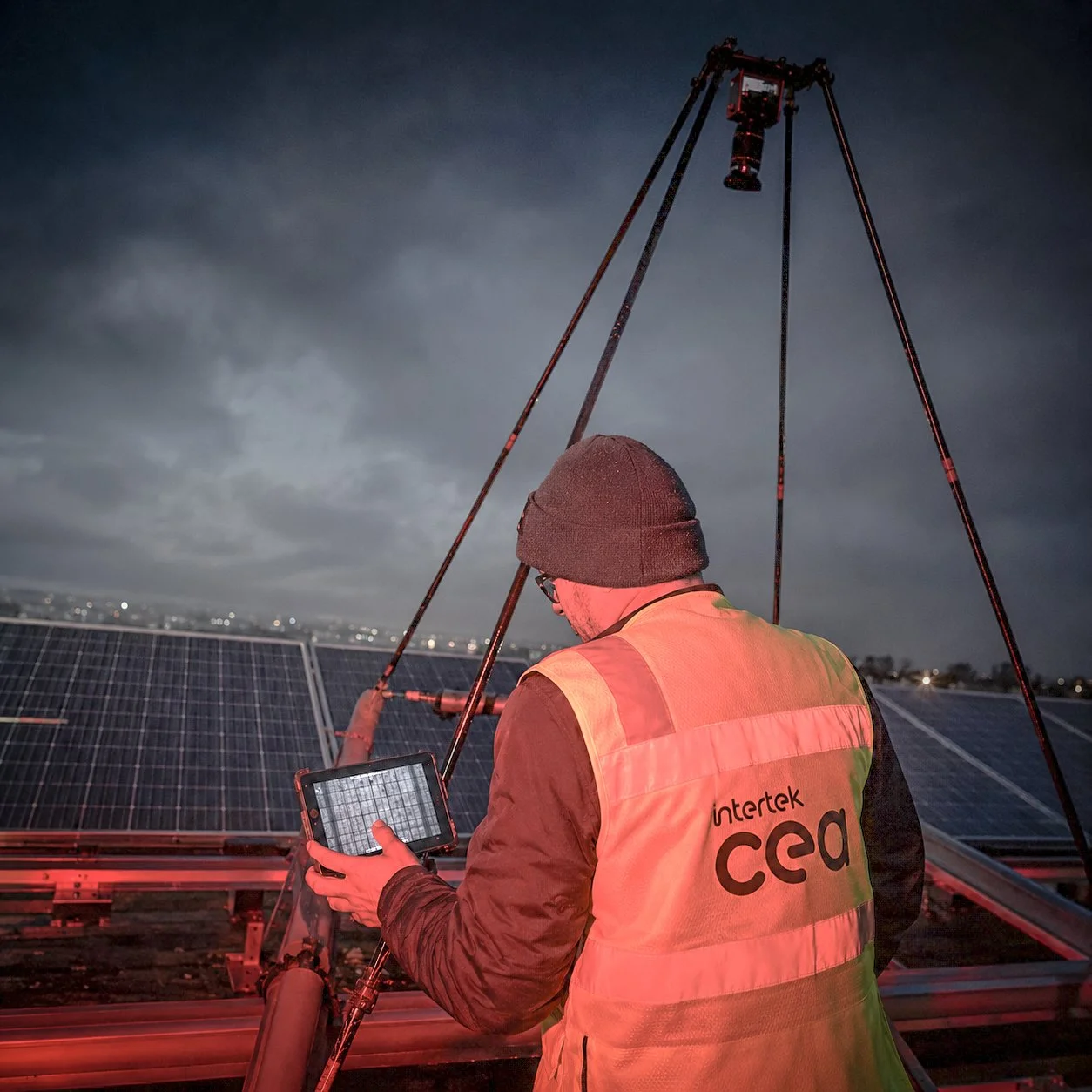
EL testing can help identify cell cracks, inactive areas, internal damage, and other module-level defects that may not be visible during a standard visual inspection.
5. Could a hidden electrical defect be involved?
Lost bypass diode issues and abnormal electrical behavior may not be obvious from visual inspection alone. LBPD testing and IV curve tracing can help narrow whether the loss is linked to hidden electrical behavior.
6. Is glass breakage part of the issue?
If cracked or broken modules are present, glass breakage inspection can help assess visible breakage patterns and whether the damage may be linked to handling, mounting, mechanical stress, weather, or other site conditions.
7. How should findings be mapped?
Before fieldwork starts, it helps to agree how findings will be mapped: by module, string, table, inverter block, GPS location, or the site’s own naming conventions.
What we may test
The right investigation method depends on the loss pattern, the suspected cause, and the level of evidence needed to support repair, warranty, or root-cause decisions. Intertek CEA may combine IR thermography, EL testing, visual inspection, LBPD testing, IV curve tracing, and glass breakage inspection.
| Method | What it helps identify | When it is useful |
|---|---|---|
| Infrared (IR) thermography | Hotspots, thermal anomalies, affected modules or strings, failed substrings, and abnormal operating behavior under suitable field conditions. | Useful for broad screening when underperformance may be linked to thermal patterns or affected site areas. |
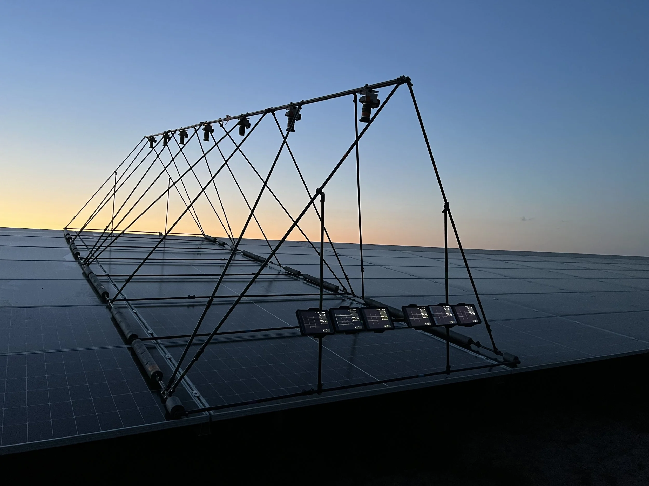
| Electroluminescence (EL) testing | Hidden cell cracks, inactive cell areas, internal module damage, interconnect issues, and cell-level defects that may not be visible from the outside. | Useful when module-level damage or degradation may be contributing to yield loss. |
| Visual inspection | Visible module damage, broken glass, corrosion, soiling, shading, connector issues, installation issues, and site-level observations. | Useful for confirming visible physical causes that may affect performance or point to a deeper root-cause issue. |
| Lost Bypass Diode (LBPD) testing | Lost or defective bypass diode behavior that can remain hidden during routine inspection and may create hotspot risk under shading. | Useful when hidden bypass diode issues may be contributing to abnormal module behavior, hotspots, or unexplained losses. |
| IV curve tracing | Electrical performance behavior of selected modules, strings, or sample groups. | Useful when yield loss needs to be confirmed through electrical performance measurements. |
| Glass breakage inspection | Glass cracks, impact damage, edge damage, breakage patterns, and visible clues that may point to mechanical stress, installation conditions, handling damage, or event-related damage. | Useful when cracked or broken modules may be contributing to underperformance, safety risk, warranty questions, or root-cause review. |
The exact method mix depends on the loss pattern, site access, system status, suspected fault type, and whether the results need to support repair planning, warranty discussions, or deeper root-cause analysis.