Services > Field Testing > Ultraviolet Fluorescence Inspection (UVF)
Ultraviolet Fluorescence Inspection (UVF)
Have a Question or Need Assistance?
Find signs of hidden damage in older PV modules without energizing the system
Cell cracks and material changes are not always visible from the surface. On older PV assets, these issues can remain undetected until they contribute to performance loss, recurring defects, or maintenance concerns.
Ultraviolet fluorescence, or UVF, uses a UV light source and specialized camera to reveal patterns in the module materials. These patterns can help identify cell cracks, moisture-related changes, signs of previous overheating, and other defects in field-aged modules.
Unlike electroluminescence testing, UVF does not require current injection or electrical interaction with the PV system.
When this inspection helps
You are assessing an older operating PV asset.
Cell cracking is suspected but current injection is not practical or preferred.
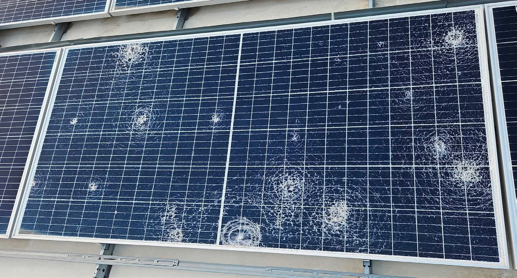
Hail, mechanical loading, walking on modules, or another event may have caused damage.
Snail trails or other visible changes suggest underlying cell cracks.
Moisture ingress, encapsulant changes, sealing issues, or corrosion are suspected.
You need a non-contact alternative to EL testing.
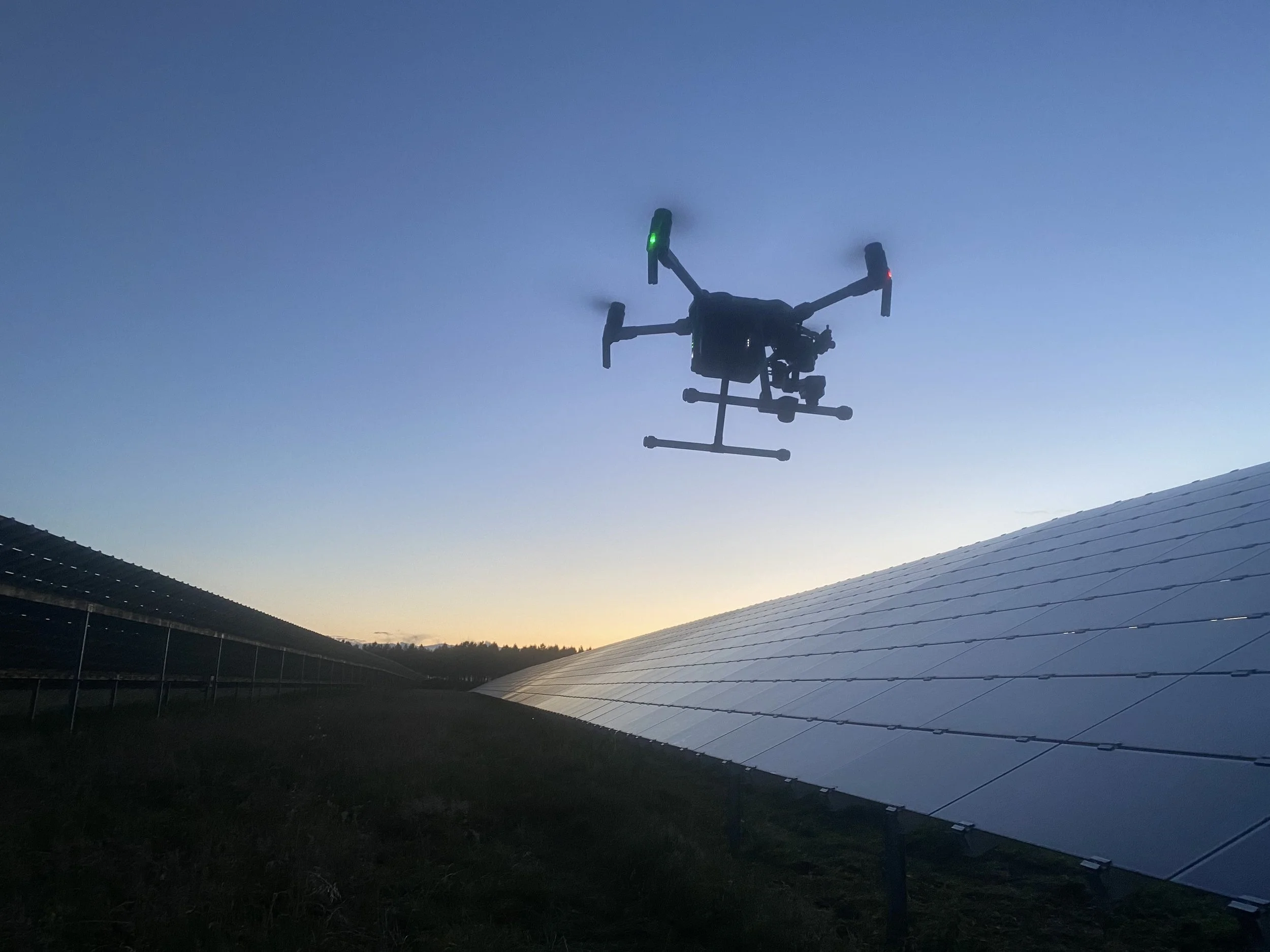
Access conditions require a pole-, tripod-, handheld-, or drone-based approach.
What UVF can help identify
Cell cracks
Cracks can change how moisture and other environmental factors interact with the module’s polymer layers. In UVF images, this can create visible bands or patterns around the affected cells.
UVF may also reveal cracks beneath busbars or interconnect wires that can be difficult to identify with other imaging methods.
Signs of older damage
The fluorescence pattern develops over time. Stronger and wider markings can indicate that a crack or defect has been present for longer, while weak patterns may suggest more recent damage.
UVF provides an indication of defect age, not an exact date.
Previous overheating
Bright or discoloured cells may indicate that a cell has operated at elevated temperature. Possible causes include shading, reduced active cell area, interconnection problems, or other module-level issues.
Moisture and material changes
UVF can help reveal patterns associated with moisture ingress, sealing problems, encapsulant changes, delamination, or corrosion. Additional testing may be needed to confirm the underlying cause.
Which modules are suitable for UVF?
UVF is most effective on older glass/foil modules, where moisture ingress and changes in the polymer layers create a visible fluorescence response.
The method is not expected to be as effective on glass/glass modules, because the material structure does not allow the same fluorescence patterns to develop.
New modules may also show little or no useful fluorescence because the material changes needed for imaging have not yet developed.
How the inspection works
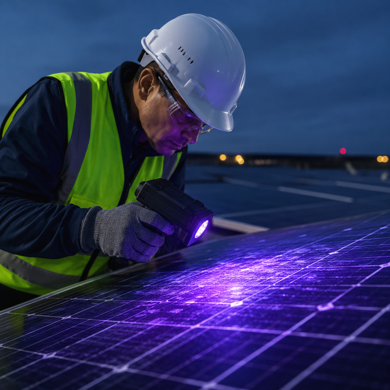
Testing takes place in darkness. A UV lamp illuminates the module while a specialized camera records the reflected fluorescence pattern. Both the UV light source and camera need to be positioned at the correct angle and close enough to the module to capture a useful image.
Depending on site access, Intertek CEA may use:
Handheld equipment
High tripods or pole-mounted systems
Drone-mounted equipment
Handheld inspection is usually the simplest option. High tripods are preferred when direct access is difficult but the equipment can still be positioned close to the modules.
Drone-based UVF is also possible, but carrying both the UV lamp and camera adds payload and reduces battery life. It is therefore mainly used where rooftop angle, access restrictions, or site layout make ground-based inspection impractical.
UVF compared with EL testing
UVF and EL can both help identify cell cracks, but they work differently.
UVF inspection
Does not require current injection
Does not require electrical interaction with the system
Can support faster, non-contact screening
Is mainly suitable for older glass/foil modules
Can provide an indication of whether damage is older or more recent
EL testing
Requires the modules or strings to be energized
Works on both new and older modules
Provides more detailed information about active cell area and crack severity
Is better suited when high-resolution electrical condition evidence is needed
The right method depends on module construction, asset age, accessibility, and the question the inspection needs to answer.
How we decide the right scope
The inspection approach depends on:
Module age and construction
Whether the modules are glass/foil or glass/glass
The suspected defect or damaging event
Roof angle, array layout, and site accessibility
Whether handheld, tripod, or drone access is practical
The required image detail and site coverage
Whether EL, thermography, visual inspection, or electrical testing is also needed
Latest Field Inspection Insights